

Introduction: Homemade Realtime GPS Tracker (SIM800L, Ublox NEO-6M, Arduino)
So you have got a GSM module lying around like me? Also a GPS-tracker?
We think the same!
In this instructables, I will try to guide you how to accomplish your goal from a newbie's perspective.
As I had no previous electrical engineering knowledge (to be honest, the project doesn't need that much,but nah), and had no clue how to make a device which pumps data real-time to a webserver, I encountered numerous problems. Still, I eventually managed to get things to work.
So, in this tutorial, I want to emphasise the mistakes a starter can make, and build-up the project accordingly.
Remember: Always be careful while you work with electricity!
NOTE: I am not professional. The code may be not sophisticated enough for all of your need. The project is intented to be a "hobby project", but! it worked for me. And if it worked for me, it would work for you too!
Step 1: Prerequisites


GSM MODULE - SIM800L
- Pretty tiny, easy-to-use
- Capable of using mobile internet (GPRS)
- Cheap
GPS MODULE - Ublox NEO6M
- Also small
- Handles its job very well
A microcontroller - can be anything - you could use the famous Arduino Uno or the Nano to free up some space
Battery - I used a 18650 cell as the main, and only power source (Nominal 3.7V)
Battery holder - why? - because soldering an 18650 battery is pretty dangereous because of the heat.
DC-DC Boost Converter Step Up Module 5V - Must have, since the Arduino I used needs 5V
Tools, basic stuff which can come in handy:
Wires, soldering iron, breadboard for testing
Step 2: Main Concept
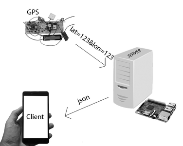
The main concept of the system is the following:
It consists of 3 parts:
- A device - which have the proper GPS-Coordinates and can connect to a server remotely and send data to it
- A webserver - which can receive incoming data - store it - and serve other clients
- The platform - where we can view the coordinates - Ideally it should be now a mobile application, or a website
Step 3: The SIM800L Module
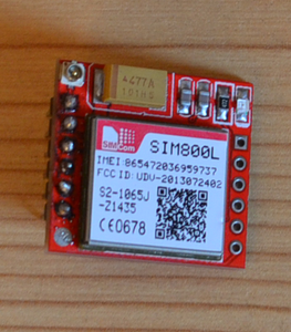
I had hard times with the module.
I would like to start with some characteristics and references.
According to the datasheet:
- It operates between 3.4V - 4.4V
- It can send SMS, make voice calls to other phones, and even connect to the Internet!
- We can communicate with it via AT-commands!
- It can use up to 2A at peak times! Note: you probably won't be able to measure it with a multimeter - because of its low sampling rates
My experience is that the SIM800L below 3.8V doesn't really work.
For futher information visit: datasheet
So your job is to provide at least 3.8V to the module (ideally 4V), a power supply which outputs at least 2A.
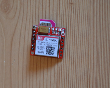
Before using the module in the final device, I suggest you establish communication with your SIM800L and your computer to make sure your device is working properly.
First things first, plug in the SIM Card like in the picture above.
To connect it with your PC, you can use an USB to TTL converter or an Arduino.
Now, I go with the Arduino.
Connect the SIM800L VCC and GND to your power source terminals.
Connect TX to Arduino 10th digital pin, RX to arduino 11th digital pin.
Download the code, I linked in this step.
With the code, you can send commands, and get them back, on your Serial Monitor.
Some simple commands:
AT --> Returns OK, if connection is OK.
ATD+123456789; --> Call a given phone number. Note: Don't forget to end it with a semicolon.
AT+CPIN? --> Returns SIM Card status (locked or not)
If you want to send an SMS, you need to end your input with a special character, it can be done with the '$' symbol.
For futher interesting commands I suggest you read this.
There are various commands, get familiar with them, they are really useful.
There is a red status LED which tells you what operation the SIM800L is in.
64 MS ON - 800MS OFF - SIM800L is not registered to the network.
64 MS ON - 3000MS OFF - SIM800L is registered to the network.
64 MS ON - 300MS OFF - SIM800l is in GPRS mode
If the SIM800L keeps restarting after about 8-10 blinks, it may be due to lack of efficient power supply.
If you don't get OK after AT, check wiring! If you have a multimeter, check continuity of the wires.
Check the connections of the wires and solder joints! The module will only work when blinking.
Attachments

Step 4: Ublox Neo 6m


Some characteristics
- Maximum voltage: 3.6V - I powered it with Arduino's 3.3V pin
- Max current draw is 67mA - so you can power it from arduino
- Temperature range: : -40-85 Celsius (I guess it will fit you)
The unit I ordered came with an antenna seen on the picture, I just plug that in the corresponding slot.
The device when has signals, blinks with blue LED.
First, check how a GPS works here, if you don't know.
When the device is on, and finds 3 satellites, it sends a lot of comma seperated values to the Arduino like above.
To help our job, we can use some external libararies to parse this data to be more human readable.
You can use TinyGps library or NeoGPS library. I used the 2nd one because that is morelightweight.
For testing, you have to connect the power pins to arduino 3.3V and GND.
Download this code, and use it with your GPS. RX --> Digital pin 10, TX --> Digital pin 11
Note: Don't forget to use the module outdoors, preferably when there is no cloud.
After half a minute, the device should blink and output your GPS coordinates! :)
Once, you know that your SIM800L and GPS module are working adequetly, you can go onto the next step.
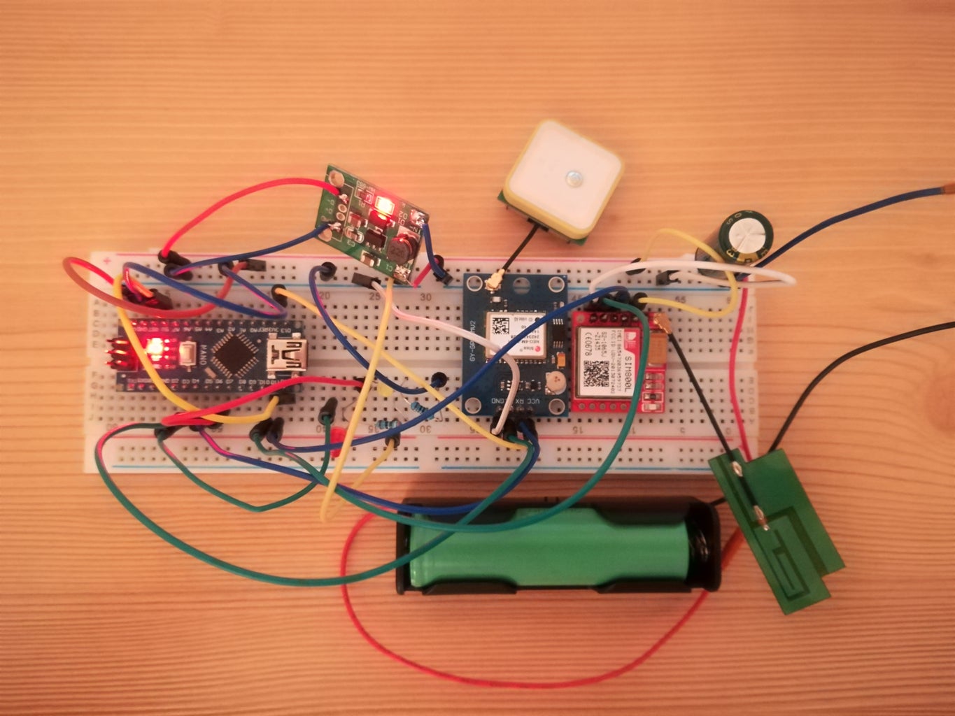
Step 5: Circuitry
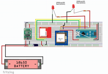
The circuit is as on the picture.
So, the 3.4V - 4.2V 18650 battery is the main power source. Sim800L gets the energy directly from it. There is a capacitor between them in paralell in order to improve the stability of the circuit.
When you choose a capacitor, you should choose a low ESR capactior.
One 5V step-up converter boosts the battery's voltage to 5V (ir is needed because Arduino works with 5V).
The 5V power rail is connected to the Nano here. The Sim800L and Neo6m are connected with Nano as on the picture. (Sim Tx-D10,SimRx-D11; NeoTX-D3,NeoRX-D4)
D12 is connected to RST, so we are able to programatically reboot the system (except the SIM800L). NOTE: This reboot methode may not be the best practice)
And lastly, two LEDS are connected to the NANO, so we can tell the user, if any error is happening.
Step 6: Code
The code is attached to the Instructables or take a look at github.
You may modify it to work properly for your needs, or you can use other's code if you want.
waitUntilResponse(); helper function was taken from his code. Check his work, and code too!
Briefly, in the setup function, we need to enable the GPRS connection of our SIM800L module. We know if it is successful if the LED blinks rapidly. (setupGPRSConnection())
In the loop function - every 15 secs the sendData() function is called - which has the HTTP request
I used query strings to push data to the webserver in this format:
ip adress/file.php?key=value&key=value e.g. http://xxx.xxx.xxx.xxx/log.php?lat=xy&lon=xy
If any error happens, the corresponding LED will light up. (SIM,GPS)
Attachments
Step 7: Webserver

For our use, a simple lightweight webserver is enough.
There are some options you can choose from:
- You could use a remote server of a company, which you probably need to pay for regularly.
- You could use your own computer. I only suggest it for testing, it is not really efficient to run it 24/7, because of energy wasting, safety issues.
- You could use a tiny computer, like Raspberry PI. Lightweight, cheap, doesn't consume much power.
I tried the 2nd, and 3rd option, they worked well. Well, the main aim is not servers of this instructables, but I hint you some advices.
If you use a PC, you use probably Windows. If I were you, I would install an Apache or XAMPP server onto it.
XAMPP already has PHP in it, besides that it also comes with HTML, Perl, and a Database Managing System. With PHP, you can make a dynamic server. If you want to use the local server you have just made from anywhere in the world, you need to assign static IP to your PC and do some portforwarding. A helpful tutorial for static IP:
And the whole portforwarding thing:
If you have a Raspberry, it is a good a practice to use it. You can get familiar with the Linux commands, and run your own server 24/7.
The OS was Raspbian Jessie with a headless setup(no keyboard, monitor) - I controlled it with my computer with SSH connection.
I used Putty to log into my Raspberry. Don't forget to change your account's password, so that others can't log into you Pi. Default is: pi, passw: raspberry.
I installed a lighttpd webserver with sqlite3. Good tutorial found here:
I used mainly PHP in the server code. With PHP you can receive data, read/write databases - encode a query into a json format, etc. ...This tutorial will help you a lot, how to manage your database with PHP.
You can view my code on github also, in the server_files folder.
And of course, you have to enable portforwarding to your Pi on your router, if you want to access that remotely.
Step 8: Ending/Experience
An enclosure is yet to be made.
My experince is that, the system works not too bad. But there are stability improvements awaiting.
If the tracker didn't work with the code I attached, don't worry. Try to make sure the SIM800L and NEO 6M are working as they should. You can modify freely my code, or look for better one. I just hope, that I could show you an example, how you can complete this project.
I accept any advice, correction from comments. Feel free to ask.

Participated in the
Microcontroller Contest


